
Learn how to build an Arduino Traffic Light Project using LEDs, resistors, and Arduino Uno. This Grade 9 STEM Activities tutorial teaches traffic signal simulation, circuit connections, coding, and real-world traffic control concepts.
Arduino Traffic Light Project (Grade 9 STEM Activities)
Introduction
The Arduino Traffic Light Project is one of the most popular beginner-friendly electronics projects for students learning Arduino programming and circuit design. Traffic lights are an essential part of modern transportation systems, helping manage vehicle movement, reduce congestion, and improve road safety.
In this project, students will create a simple traffic light simulation using an Arduino board and three LEDs representing the red, yellow, and green traffic signals. By programming the Arduino, the LEDs will switch automatically in the same sequence used by real traffic lights.
This Arduino Traffic Light Project is an excellent example of practical learning and is widely used in Grade 9 STEM Activities to teach electronics, programming, automation, and control systems.
Watch the Arduino Traffic Light Project Tutorial
Watch this step-by-step Arduino Traffic Light Project tutorial to learn how traffic signals work, how LEDs are controlled using Arduino, and how automation is used in modern traffic management systems.
Table of Contents
What is an Arduino Traffic Light Project?
The Arduino Traffic Light Project is a simple electronics project that simulates a real-world traffic signal system using LEDs and an Arduino board.
The project uses:
- Red LED (Stop Signal)
- Yellow LED (Prepare Signal)
- Green LED (Go Signal)
The Arduino controls each LED through programmed timing sequences, creating a realistic traffic signal operation.
Students learn:
- LED control
- Digital output programming
- Circuit assembly
- Timing functions
- Automation concepts
This makes the project ideal for Grade 9 STEM Activities and beginner Arduino learners.
Components Required
To build the Arduino Traffic Light Project, you need:
| Component | Quantity |
|---|---|
| Arduino Uno | 1 |
| Red LED | 1 |
| Yellow LED | 1 |
| Green LED | 1 |
| 220Ω Resistors | 3 |
| Breadboard | 1 |
| Jumper Wires | Several |
| USB Cable | 1 |

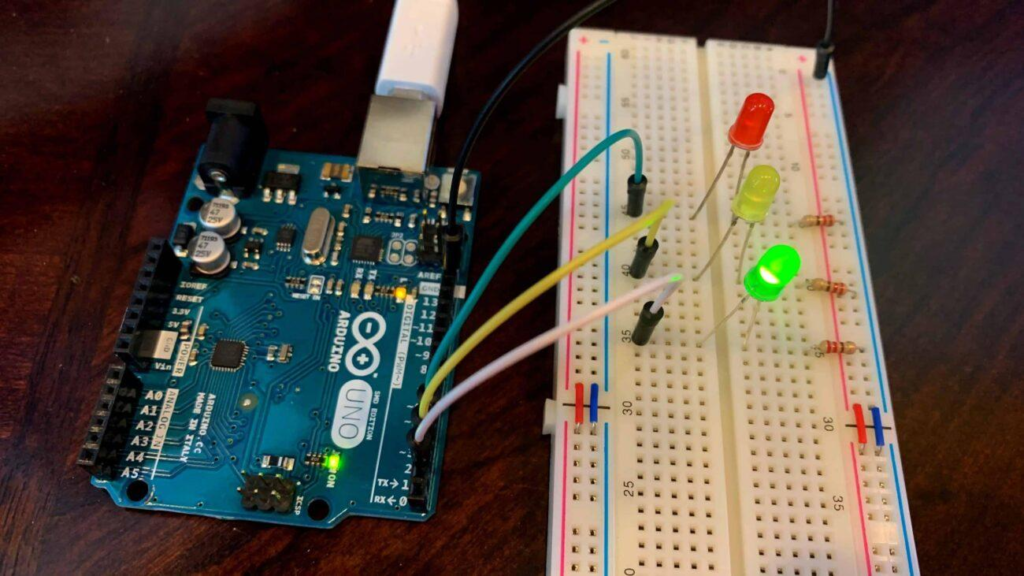
Arduino Uno connected with red, yellow, and green LEDs for traffic light simulation.
Traffic Light LED Pin Configuration
The LEDs are connected to the Arduino digital pins as shown below:
| LED Color | Arduino Pin | Function |
|---|---|---|
| Red | Pin 1 | Stop Signal |
| Yellow | Pin 2 | Prepare Signal |
| Green | Pin 3 | Go Signal |
Each LED is connected through a resistor to limit current and protect both the LED and Arduino board.
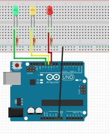
Pin configuration of LEDs connected to Arduino Uno for traffic light simulation.
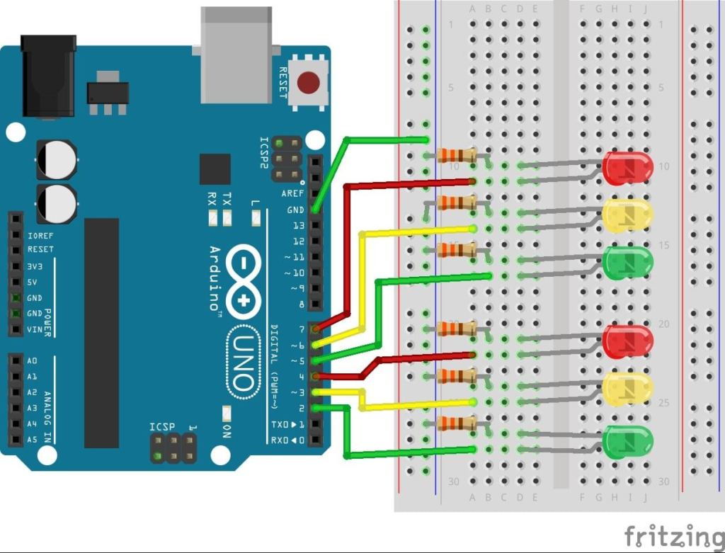
Circuit Connections
Follow these wiring steps carefully:
Step 1: Connect LED Grounds
Connect the shorter leg (negative terminal) of all LEDs to a common ground rail on the breadboard.
Step 2: Connect Arduino Ground
Connect Arduino GND to the common ground rail.
Step 3: Connect Resistors
Place a resistor in series with the positive leg of each LED.
Step 4: Connect Digital Pins
- Red LED → Pin 1
- Yellow LED → Pin 2
- Green LED → Pin 3
After completing the wiring, connect the Arduino board to your computer.
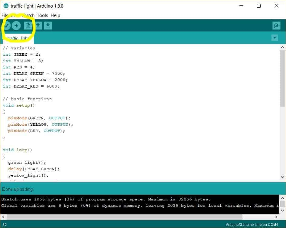
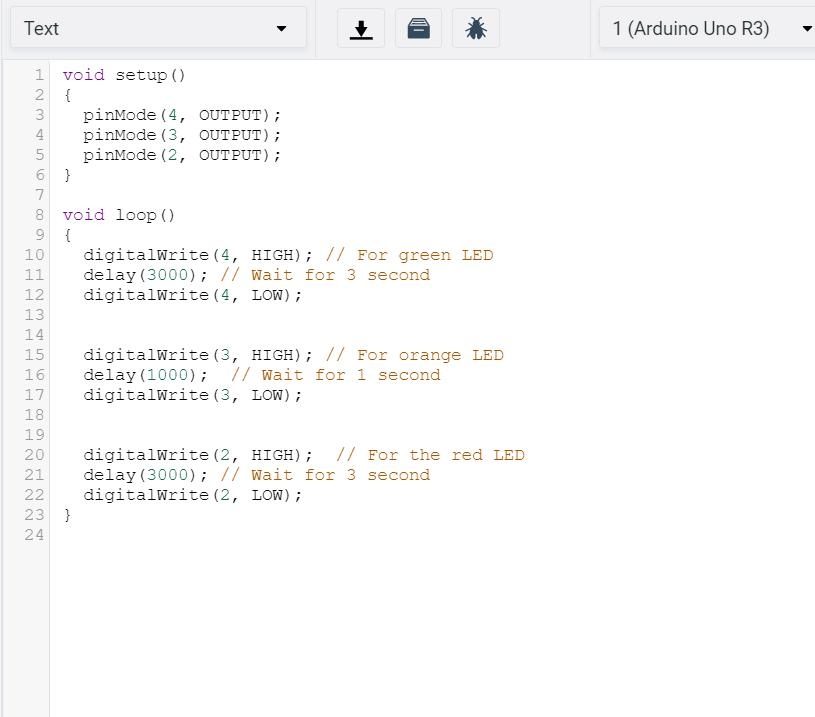
Arduino Code
Upload the following code to your Arduino board:
int red = 1;
int yellow = 2;
int green = 3;

int duration = 3000;

void setup() {

  pinMode(red, OUTPUT);
  pinMode(yellow, OUTPUT);
  pinMode(green, OUTPUT);
}

void loop() {

  digitalWrite(red, HIGH);
  delay(duration);
  digitalWrite(red, LOW);

  digitalWrite(yellow, HIGH);
  delay(duration);
  digitalWrite(yellow, LOW);

  digitalWrite(green, HIGH);
  delay(duration);
  digitalWrite(green, LOW);
}
The code continuously cycles through red, yellow, and green LEDs to simulate a real traffic signal.
Working Principle
The Arduino Traffic Light Project operates using a simple sequence.
Red Light
The red LED turns ON, signaling vehicles to stop.
Yellow Light
After the red light turns OFF, the yellow LED turns ON, indicating that the signal is about to change.
Green Light
The green LED turns ON, allowing traffic to move.
Continuous Loop
After the green light turns OFF, the cycle repeats automatically.
This sequence closely resembles how real traffic signals operate at road intersections.
Output and Results
Once the code is uploaded:
- Red LED lights up.
- After 3 seconds, red turns OFF.
- Yellow LED lights up.
- After 3 seconds, yellow turns OFF.
- Green LED lights up.
- After 3 seconds, green turns OFF.
- The cycle restarts.
Only one LED remains ON at any given time, ensuring proper traffic control logic.
Real-World Applications
The concepts learned in the Arduino Traffic Light Project are used in many real systems.
Traffic Management Systems
Control vehicle movement at intersections.
Smart Cities
Automated traffic control helps reduce congestion.
Railway Signaling
Signal systems guide train movement safely.
Industrial Automation
Sequenced control systems manage machine operations.
Educational STEM Projects
Used worldwide to teach embedded systems and programming.
Why Learn STEM Projects with RoboSiddhi?
At RoboSiddhi, we focus on hands-on learning experiences that make science and technology exciting for students.
The Arduino Traffic Light Project helps learners understand:
- Basic electronics
- Circuit design
- Arduino programming
- Automation systems
- Engineering problem-solving
Our STEM activities encourage students to explore real-world technologies through practical experimentation and project-based learning.
Frequently Asked Questions
Why are resistors used with LEDs?
Resistors limit current flow and protect LEDs and Arduino pins from damage.
Can I use Arduino Nano instead of Arduino Uno?
Yes. Any Arduino board with digital output pins can be used.
Why does only one LED turn ON at a time?
This mimics real traffic light behavior and prevents conflicting traffic signals.
Can I change the timing?
Yes. Modify the value of the duration variable to increase or decrease signal timing.
Is this project suitable for Grade 9 students?
Yes. The Arduino Traffic Light Project is one of the most popular Grade 9 STEM Activities because it combines programming, electronics, and real-world applications.
Conclusion
The Arduino Traffic Light Project is a simple yet powerful introduction to automation and embedded systems. Using only three LEDs, resistors, and an Arduino board, students can create a working traffic signal system that demonstrates real-world traffic management principles.
This project develops essential STEM skills including coding, circuit building, logical thinking, and system design. As a Grade 9 STEM Activity, it provides an engaging way to learn how modern control systems operate.
Explore more exciting Arduino projects, robotics activities, and STEM experiments with RoboSiddhi to continue your journey into technology and innovation.