
Series Parallel Circuit STEM Activity Grade 7
Series Parallel Circuit STEM Activity Grade 7 is a fun and practical electronics project that helps students understand how electrical circuits work using Arduino, LEDs, jumper wires, resistors, and breadboards. This STEM learning activity introduces students to the difference between series and parallel circuits through hands-on experimentation and coding.
In this project, students learn how LEDs behave differently in both connections. In a series circuit, all LEDs depend on one complete current path. In a parallel circuit, LEDs work independently through multiple paths. This activity combines electronics, coding, robotics, and STEM education in a beginner-friendly way for Grade 7 students.
Students can also explore robotics kits, coding boards, sensors, electronics tools, and DIY STEM activities from RoboSiddhi.
RoboSiddhi supports practical robotics and STEM education for schools and students.
Table of Contents
Introduction to Series and Parallel Circuits STEM Activity Grade 7
Series and parallel circuits are two of the most important concepts in electronics and robotics. Understanding these circuits helps students learn how electricity flows through electronic components.
In a series connection, current flows through one continuous path. If one LED stops working, the complete circuit breaks and all LEDs turn OFF.
In a parallel connection, each LED has its own independent path. If one LED fails, the remaining LEDs continue glowing normally.
This practical STEM project demonstrates both types of circuits using Arduino and LEDs.
What Students Learn in This STEM Activity
This Series Parallel Circuit STEM Activity Grade 7 project helps students learn:
- Basics of electrical circuits
- Arduino programming
- Breadboard connections
- LED polarity
- Current flow concepts
- Difference between series and parallel circuits
- Electronics troubleshooting
- Robotics fundamentals
- STEM engineering concepts
- Coding and hardware integration
Hands-on STEM learning improves creativity and technical confidence among students.
Components Required
The following components are used in this STEM electronics activity.
| Component | Purpose |
|---|---|
| Arduino Board | Controls LEDs digitally |
| Breadboard | Platform for building circuits |
| LEDs | Output light components |
| Resistors | Limit current flow |
| Jumper Wires | Make electrical connections |
| USB Cable | Upload Arduino code |
Students can find these beginner electronics components at RoboSiddhi STEM Store.
STEM Activity Grade 7 : Understanding Series Circuits
A series circuit contains only one path for electrical current flow.
The LEDs are connected one after another in sequence. Current passes through LED 1, then LED 2, and finally LED 3 before reaching the ground connection.
Features of Series Circuits
| Feature | Description |
|---|---|
| Current Path | Single path |
| Voltage Distribution | Divided among LEDs |
| LED Brightness | Lower brightness |
| Failure Impact | Entire circuit stops |
The tutorial compares a series circuit to a train moving on one railway track. If the track breaks anywhere, the train cannot continue moving.
Understanding Parallel Circuits
A parallel circuit contains multiple independent paths for current flow.
Each LED receives the same voltage independently through separate branches. If one LED fails, the other LEDs continue glowing because current still flows through the remaining paths.
Features of Parallel Circuits
| Feature | Description |
|---|---|
| Current Path | Multiple paths |
| Voltage Distribution | Equal voltage |
| LED Brightness | Brighter LEDs |
| Failure Impact | Only one LED affected |
The instructor compares parallel circuits to multiple roads. If one road is blocked, vehicles can use another route.
Arduino Coding Setup
The Arduino IDE is used to control the LEDs digitally.
Students learn how to:
- Open Arduino IDE
- Create a new sketch
- Define output pins
- Use digitalWrite()
- Add delay timing
- Upload code to Arduino
The LEDs are connected to Arduino digital pin 4.
Arduino LED Blink Code
void setup() {
  pinMode(4, OUTPUT);
}

void loop() {
  digitalWrite(4, HIGH);
  delay(1000);

  digitalWrite(4, LOW);
  delay(1000);
}
Students can download Arduino IDE from the official Arduino website.
https://www.arduino.cc/en/software
Building the Series Circuit
The series circuit is assembled carefully on the breadboard.
Step-by-Step Series Connections
- Connect LED 1 positive leg to Arduino pin 4
- Connect LED 1 negative leg to LED 2 positive leg
- Connect LED 2 negative leg to LED 3 positive leg
- Connect LED 3 negative leg to Arduino GND
- Upload the Arduino code
All LEDs share one current path in this arrangement.
Image: Series Circuit Setup

Observing the Series Circuit
When the code is uploaded:
- All LEDs glow together
- LEDs blink simultaneously
- Brightness appears lower compared to parallel circuits
If one LED is removed:
- Current flow stops completely
- All LEDs turn OFF
This demonstrates the dependency of components in a series circuit.
Building the Parallel Circuit
The series circuit is removed before constructing the parallel circuit.
Step-by-Step Parallel Connections
- Connect all LED positive legs together
- Connect resistor before the positive line
- Connect positive line to Arduino pin 4
- Connect all negative legs to GND
- Upload the same Arduino code
Each LED receives an independent electrical path.
Image: Parallel Circuit Setup

Observing the Parallel Circuit
When powered:
- LEDs glow brighter
- Removing one LED does not affect others
- Current flows independently through each branch
Students visually observe how parallel circuits are more reliable than series circuits.
Why Parallel LEDs Glow Brighter
Parallel LEDs glow brighter because each LED receives full supply voltage.
In a series circuit:
- Voltage divides among LEDs
- Current passes through all LEDs sequentially
- Brightness decreases
In a parallel circuit:
- Every LED gets equal voltage
- LEDs maintain stronger brightness
- Current flows separately through branches
This concept is important in electrical engineering and robotics systems.
Importance of Resistors
Resistors are critical electronic components used to limit current flow.
Without resistors:
- LEDs may burn out
- Components may overheat
- Circuits can fail
Benefits of Using Resistors
| Benefit | Explanation |
|---|---|
| Current Control | Protects LEDs |
| Circuit Safety | Prevents overheating |
| Stable Operation | Improves reliability |
The resistor is connected before the LEDs to ensure safe operation.
Breadboard Basics
A breadboard allows students to build circuits without soldering.
Breadboard Advantages
- Easy to use
- Reusable
- Safe for beginners
- Fast circuit testing
- Ideal for STEM projects
Breadboards are commonly used in robotics, electronics, and Arduino learning.
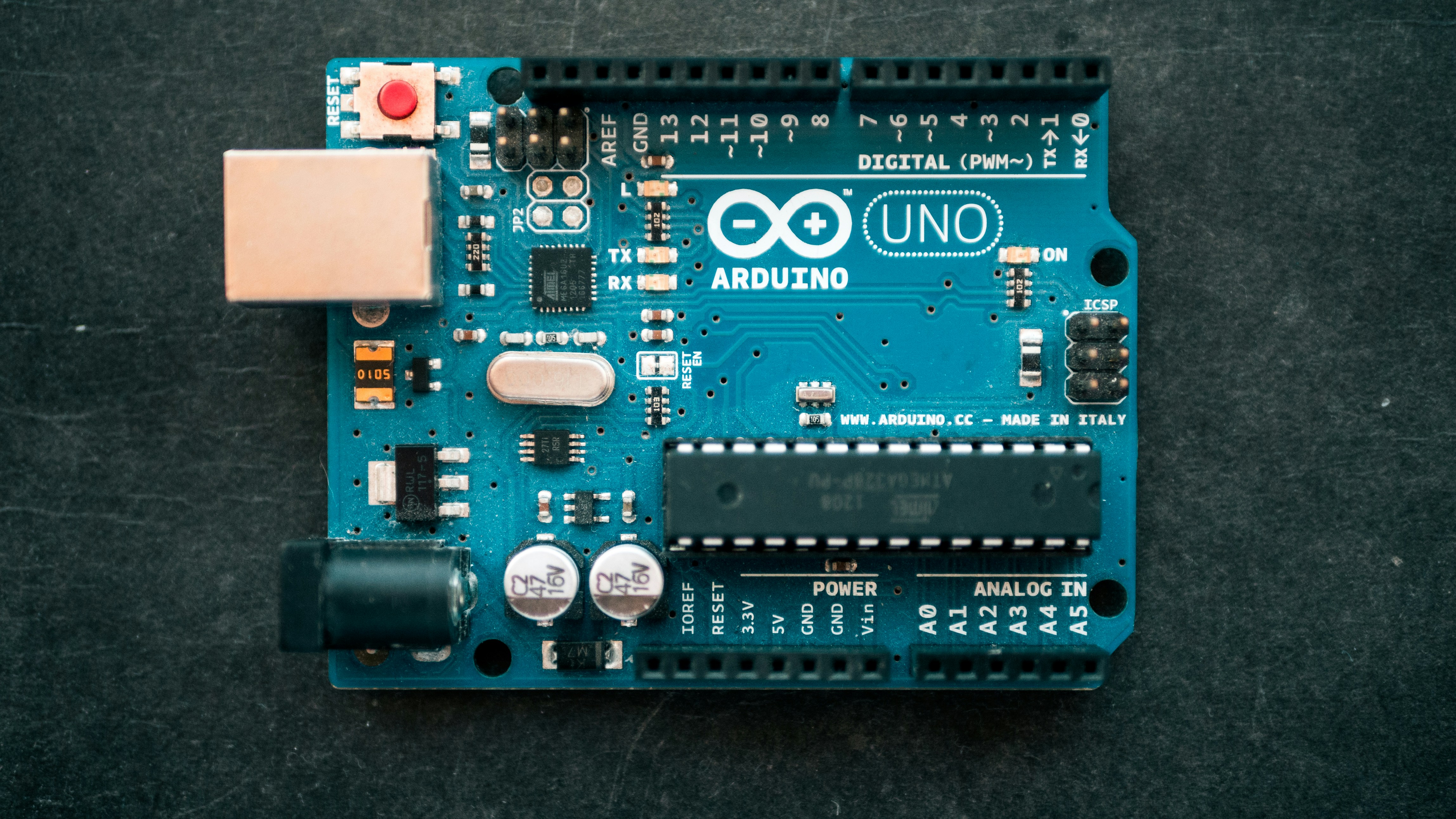
Image: Arduino Breadboard STEM Activity
STEM Learning Benefits
This electronics activity supports practical STEM education.
Students improve:
- Logical thinking
- Engineering skills
- Coding abilities
- Creativity
- Problem-solving
- Robotics understanding
- Technical confidence
Hands-on STEM learning makes science and electronics more engaging.
Robotics and Electronics Applications
Series and parallel circuits are used in many real-world systems.
Real-Life Applications
| Application | Circuit Type |
|---|---|
| Home Wiring | Parallel |
| Decorative Lights | Series |
| Robotics Projects | Parallel |
| Flashlights | Series |
| Automotive Lighting | Parallel |
Students begin understanding how electronics are used in modern technology.
RoboSiddhi STEM Learning Resources
Students interested in robotics and STEM education can explore beginner-friendly learning products from RoboSiddhi.
RoboSiddhi provides:
- Robotics kits
- STEM learning tools
- Arduino boards
- Sensors and modules
- DIY electronics kits
- Coding projects
- Beginner robotics activities
Official Website: https://robosiddhi.com/
Internal Learning Resources:
https://www.youtube.com/@robosiddhi/videos
Troubleshooting Common Problems
Sometimes LEDs may not glow properly.
Common Problems and Solutions
| Problem | Solution |
|---|---|
| LED not glowing | Check polarity |
| Wrong jumper connections | Reconnect wires |
| Loose breadboard wiring | Tighten connections |
| Missing resistor | Add resistor |
| Incorrect Arduino pin | Verify code |
Troubleshooting helps students improve electronics understanding.
Image: STEM Robotics Learning

Conclusion
Series Parallel Circuit STEM Activity Grade 7 is an excellent beginner electronics and robotics project that teaches students the difference between series and parallel circuits using Arduino and LEDs.
Students learn how current flows differently in both connections, why parallel LEDs glow brighter, and how Arduino coding controls electronic components. The project combines STEM education, coding, robotics, and electronics into one practical learning experience.
This hands-on activity develops engineering skills, technical creativity, and problem-solving abilities while making electronics fun and interactive for Grade 7 students.
For more STEM kits, Arduino boards, sensors, coding tools, and robotics learning resources, students can explore RoboSiddhi https://robosiddhi.shop/