
Learn how to build a Raspberry Pi Push Button LED Control Project using GPIO pins and Python programming. This Grade 9 STEM Activities tutorial teaches button input, LED output, and Raspberry Pi interfacing.
Raspberry Pi Push Button LED Control Project: 5 Easy Steps for Grade 9 STEM Activities
Introduction
The Raspberry Pi Push Button LED Control Project is a simple and exciting electronics project that teaches students how to control an LED using a push button and Raspberry Pi GPIO pins. This project introduces the fundamentals of hardware interfacing, digital input and output, and Python programming.
In this Raspberry Pi Push Button LED Control Project, pressing a push button turns an LED ON, while releasing the button turns the LED OFF. This real-time interaction between hardware and software helps students understand how embedded systems work.
As one of the most engaging Grade 9 STEM Activities, this project combines electronics, programming, and problem-solving skills through hands-on learning.
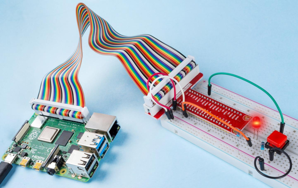
Raspberry Pi connected with a push button, LED, resistor, and breadboard.
Table of Contents
YouTube Video
Step-by-step Raspberry Pi Push Button LED Control Project tutorial showing circuit connections, GPIO programming, Python coding, and real-time button-controlled LED operation.
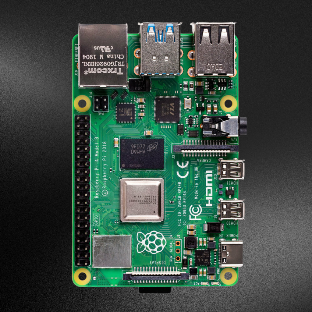
What is Raspberry Pi?
Raspberry Pi is a compact single-board computer that can run a complete operating system while also controlling electronic devices through its GPIO (General Purpose Input Output) pins.
The Raspberry Pi is widely used in:
- Robotics
- IoT Projects
- Automation Systems
- Smart Home Applications
- Educational STEM Activities
The GPIO pins allow Raspberry Pi to communicate with sensors, buttons, LEDs, motors, and many other electronic components.
Components Required
To build the Raspberry Pi Push Button LED Control Project, you need the following components:
| Component | Quantity |
|---|---|
| Raspberry Pi | 1 |
| Push Button | 1 |
| LED | 1 |
| Resistor (220Ω) | 1 |
| Breadboard | 1 |
| Jumper Wires | Several |
These components are inexpensive and perfect for beginner electronics projects.
Circuit Connections for Raspberry Pi Push Button LED Control Project
Follow these hardware connection steps carefully.
LED Connections
- Connect the LED positive terminal (Anode) to GPIO 17.
- Connect the LED negative terminal (Cathode) to the resistor.
- Connect the resistor to Ground.
Push Button Connections
- Connect one terminal of the push button to GPIO 18.
- Connect the other terminal of the push button to Ground.
Ground Connection
- Connect the Raspberry Pi GND pin to the breadboard ground rail.
Connection Table
| Component | Raspberry Pi Connection |
|---|---|
| LED Anode (+) | GPIO 17 |
| LED Cathode (-) | Resistor |
| Resistor | Ground |
| Push Button | GPIO 18 |
| Ground Rail | Raspberry Pi GND |
This completes the hardware setup for the Raspberry Pi Push Button LED Control Project.
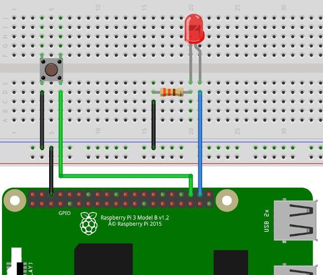
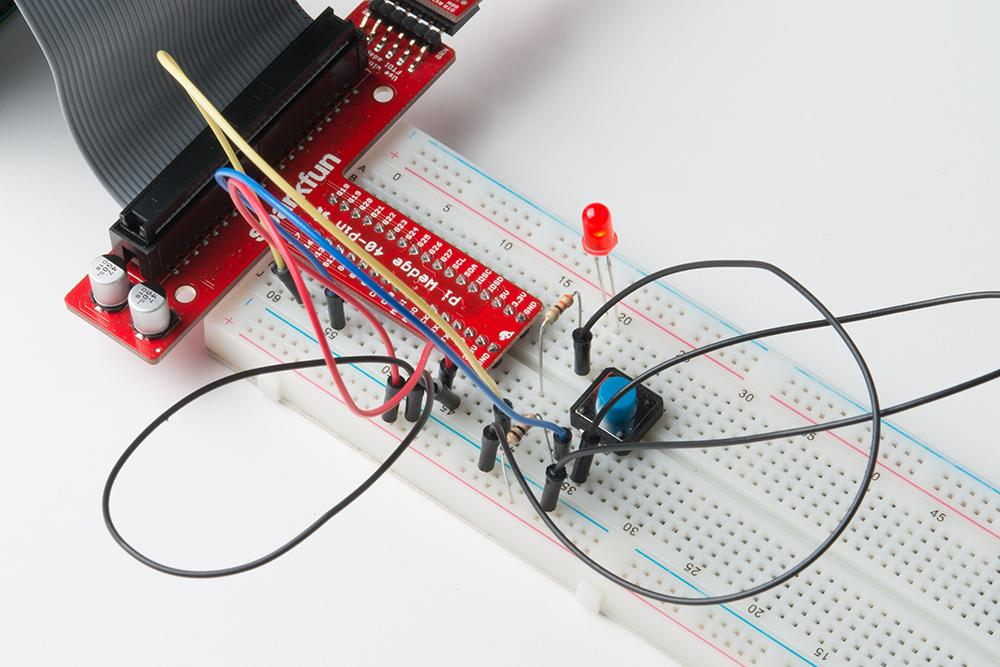
Circuit connections between Raspberry Pi, push button, LED, resistor, and breadboard.
How the Raspberry Pi Push Button LED Control Project Works
The Raspberry Pi Push Button LED Control Project uses one GPIO pin as an input and another GPIO pin as an output.
Input Pin
GPIO 18 reads the push button state.
Output Pin
GPIO 17 controls the LED.
Logic Flow
- User presses the push button.
- GPIO 18 detects the button press.
- Python program reads the button state.
- GPIO 17 is set HIGH.
- LED turns ON.
When the button is released:
- GPIO 18 changes state.
- Program detects the release.
- GPIO 17 is set LOW.
- LED turns OFF.
This creates instant LED control using the push button.
Raspberry Pi GPIO Pins Explained
GPIO stands for General Purpose Input Output.
GPIO pins can work as:
Input Pins
Used to receive signals from:
- Push Buttons
- Sensors
- Switches
Output Pins
Used to control:
- LEDs
- Buzzers
- Motors
- Relays
In the Raspberry Pi Push Button LED Control Project, GPIO 18 acts as an input pin while GPIO 17 acts as an output pin.
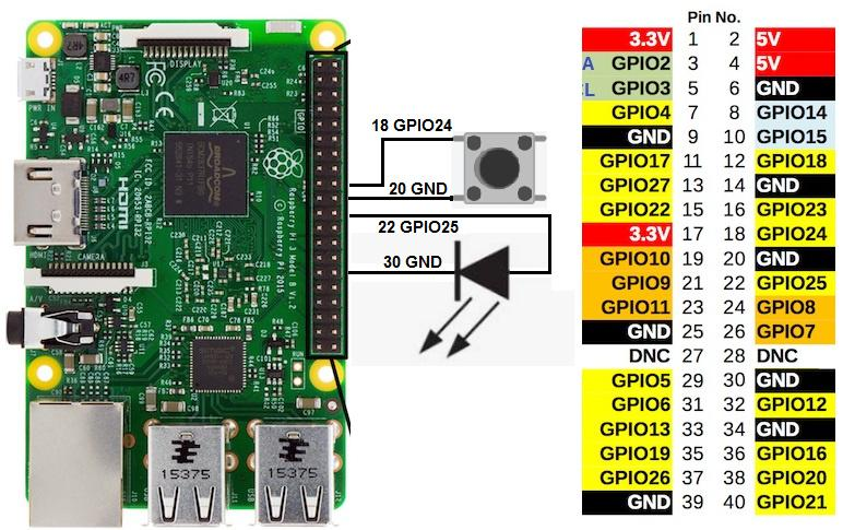
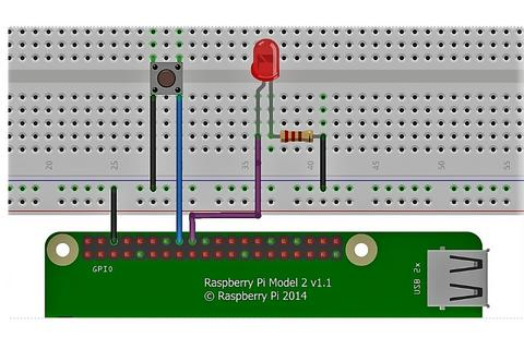
GPIO 17 connected to LED and GPIO 18 connected to push button for input control.
Python Program for Raspberry Pi Push Button LED Control Project
The project is programmed using Python in the Thonny IDE.
Import Required Libraries
import RPi.GPIO as GPIO
import time
Set GPIO Mode
GPIO.setmode(GPIO.BCM)
Define Pins
LED = 17
BUTTON = 18
Configure GPIO Pins
GPIO.setup(LED, GPIO.OUT)
GPIO.setup(BUTTON, GPIO.IN)
Main Program Logic
while True:
    if GPIO.input(BUTTON) == False:
        GPIO.output(LED, GPIO.HIGH)
    else:
        GPIO.output(LED, GPIO.LOW)
This code continuously checks the button state and controls the LED accordingly.
Running the Raspberry Pi Push Button LED Control Project
Step 1
Open Thonny IDE on Raspberry Pi.
Step 2
Create a new Python file.
Step 3
Paste the project code.
Step 4
Save the file.
Step 5
Run the program.
Step 6
Press the push button and observe the LED.
The LED should turn ON when the button is pressed and OFF when it is released.
Output and Results
After successfully running the Raspberry Pi Push Button LED Control Project, you will observe:
- LED turns ON when the button is pressed.
- LED turns OFF when the button is released.
- GPIO pins respond instantly.
- Hardware and software work together smoothly.
This demonstrates successful GPIO interfacing using Raspberry Pi.
Applications of Project
The concepts learned in this project can be applied to many real-world systems.
Home Automation
Control lights and appliances using switches.
Security Systems
Trigger alarms and notifications.
Industrial Control Systems
Operate machinery using control buttons.
Robotics
Use buttons to control robot actions.
IoT Devices
Create interactive smart devices.
The Raspberry Pi Push Button LED Control Project serves as a foundation for more advanced embedded systems.
Why Learn STEM Projects with RoboSiddhi?
RoboSiddhi provides hands-on STEM learning experiences that help students understand technology through practical projects.
Benefits include:
- Learning by doing
- Real-world electronics experience
- Python programming skills
- Raspberry Pi project development
- Problem-solving and innovation
Projects like the Raspberry Pi Push Button LED Control Project make learning interactive and enjoyable.
Frequently Asked Questions
What is the purpose of the Raspberry Pi Push Button LED Control Project?
The project teaches how to use GPIO pins to read button inputs and control LED outputs using Python programming.
Which GPIO pins are used?
- GPIO 17 → LED Output
- GPIO 18 → Push Button Input
Why is a resistor used?
The resistor limits current and protects the LED from damage.
Which software is used?
Python programming is performed using Thonny IDE.
Is this project suitable for beginners?
Yes. The Raspberry Pi Push Button LED Control Project is ideal for beginners learning electronics and programming.
Can this project be expanded?
Yes. Additional LEDs, sensors, buzzers, and motors can be added to create advanced Raspberry Pi projects.
Internal Links
You may also like:
- Raspberry Pi LED Blinking Project
- ESP32 Bluetooth LED Control Project
- ESP32 WiFi Controlled Street Light Project
- Arduino Traffic Light Project
- Arduino DHT11 Temperature Monitoring Project
Conclusion
The Raspberry Pi Push Button LED Control Project is a beginner-friendly electronics project that demonstrates how a push button can control an LED using Raspberry Pi GPIO pins and Python programming. Through simple hardware connections and easy-to-understand code, students learn essential concepts such as digital inputs, digital outputs, GPIO configuration, and real-time hardware interaction.
As one of the most practical Grade 9 STEM Activities, the Raspberry Pi Push Button LED Control Project helps learners develop foundational skills in electronics, programming, robotics, and embedded systems while encouraging creativity and hands-on experimentation.