
ESP32 Smart Monitoring System using a DST module to display real-time sensor data through a web browser.
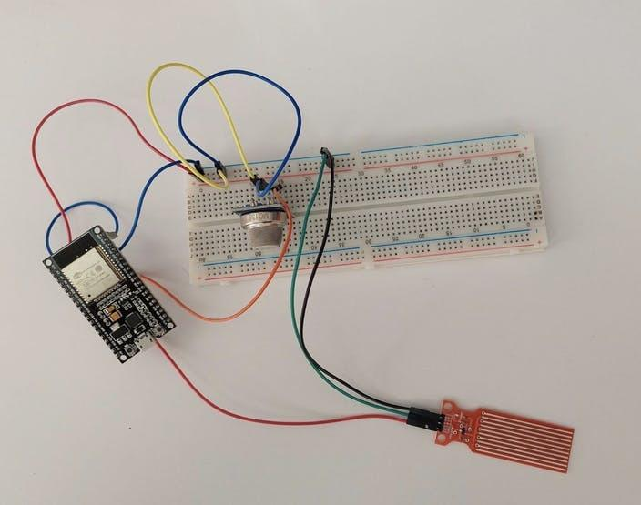
The ESP32 Smart Monitoring System is an innovative IoT project that demonstrates how sensor data can be monitored wirelessly in real time. By combining an ESP32 microcontroller with a DST module, users can collect data and access it remotely through a web browser. This project introduces important concepts such as Wi-Fi connectivity, embedded web servers, sensor interfacing, and real-time monitoring.
Whether you are a beginner exploring IoT or a student working on a STEM project, this activity provides a practical understanding of how modern monitoring systems work.
Introduction
The Internet of Things (IoT) has transformed the way devices communicate and share information. Smart monitoring systems are used in homes, industries, agriculture, and environmental applications to collect and display data remotely.
In this project, the ESP32 microcontroller acts as the central controller. It connects to a Wi-Fi network, reads data from the DST module, and hosts a web server that displays live information. Users can access this information through a smartphone, tablet, or computer connected to the same network.
The project demonstrates how wireless communication can simplify monitoring tasks and improve accessibility to real-time information.
The ESP32 microcontroller serves as the main controller in the ESP32 Smart Monitoring System.
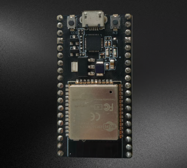
Table of Contents
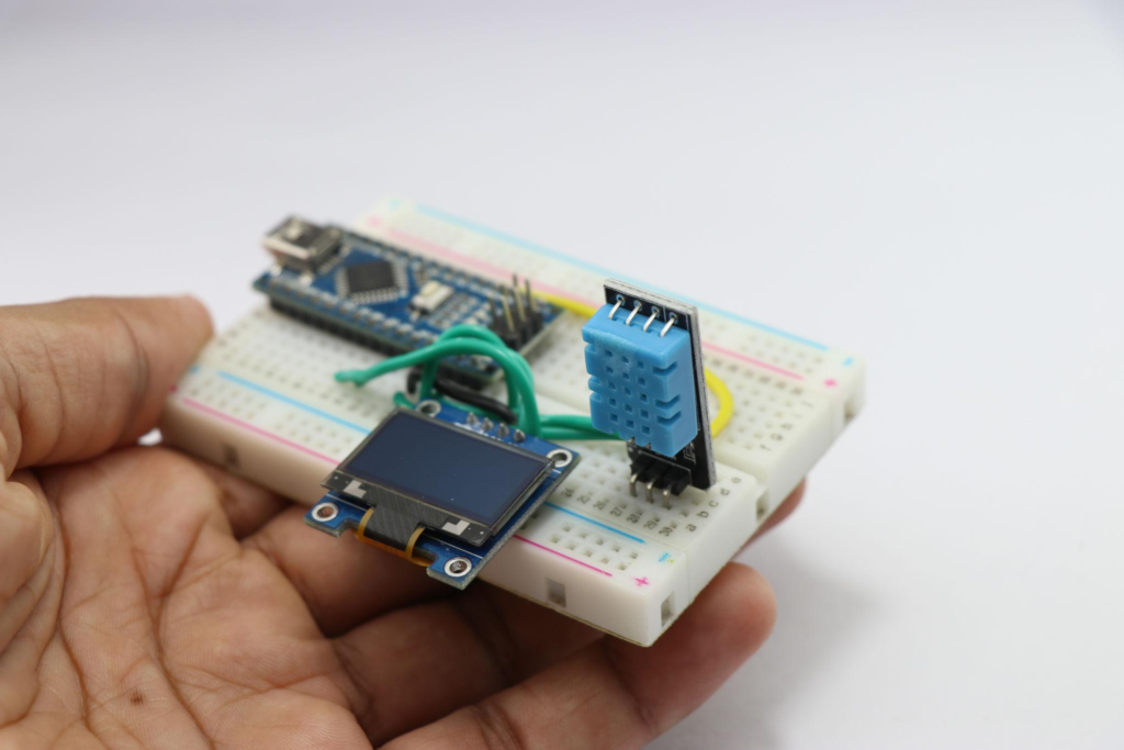
Components Required for ESP32 Smart Monitoring System
To build the ESP32 Smart Monitoring System, you will need the following components:
- ESP32 Development Board
- DST Module
- Breadboard
- Jumper Wires
- USB Cable
- Computer with Arduino IDE Installed
- Smartphone or Laptop
- Wi-Fi Network or Hotspot
Essential components required to build the ESP32 Smart Monitoring System.
Working Principle
The ESP32 collects information from the connected DST module through its signal pin. The data is processed by the microcontroller and transmitted through a built-in web server.
The system connects to a Wi-Fi network using predefined SSID and password credentials entered in the program. Once connected, the ESP32 receives an IP address and starts hosting a local web page.
When users open the displayed IP address in a web browser, they can view real-time information transmitted from the monitoring system.
This setup eliminates the need for direct physical access to the sensor and enables convenient wireless monitoring.
Circuit Connections of ESP32 Smart Monitoring System
Proper wiring is essential for successful operation of the project.
Connection Details
| DST Module Pin | ESP32 Connection |
|---|---|
| Signal Pin | GPIO 4 |
| GND | GND |
| VCC | 5V |
Assembly Steps
- Place the ESP32 on the breadboard.
- Position the DST module on the breadboard.
- Connect the signal pin of the DST module to GPIO Pin 4 of the ESP32.
- Connect the ground pin of the DST module to the ESP32 ground.
- Connect the VCC pin of the DST module to the 5V supply.
- Verify all jumper wire connections carefully.
- Connect the ESP32 to the computer using a USB cable.
After completing these connections, the hardware setup is ready for programming.
Programming the ESP32 Smart Monitoring System
The ESP32 is programmed using Arduino IDE.
The code includes:
- Required ESP32 libraries
- Wi-Fi configuration settings
- SSID and Password credentials
- Server initialization
- Sensor data reading functions
- Web page generation for displaying live data
Before uploading the program, update the code with your Wi-Fi network credentials.
Configuration Parameters
const char* ssid = "Your_WiFi_Name";
const char* password = "Your_WiFi_Password";
Replace these values with your own network information before uploading.
Uploading the Code
Follow these steps to upload the program successfully:
- Open Arduino IDE.
- Select the ESP32 development board.
- Choose the correct COM port.
- Connect the ESP32 using a USB cable.
- Click the Upload button.
- Press the Boot button once when required.
- Wait for the upload process to complete.
Once the upload is successful, the ESP32 will restart automatically.
Testing the System
After uploading the code:
- Open the Serial Monitor.
- Reset the ESP32 board.
- Wait for the device to connect to Wi-Fi.
- Observe the displayed IP address.
- Ensure that your smartphone or laptop is connected to the same network.
The Serial Monitor will display information similar to:
Connecting to WiFi...
WiFi Connected
IP Address: 192.168.1.xxx
This confirms that the ESP32 is connected successfully.
Viewing Live Data
Once the IP address appears:
- Open a web browser on your mobile phone or laptop.
- Enter the ESP32 IP address into the browser.
- Press Enter.
The web page hosted by the ESP32 will load and display real-time information received from the DST module.
This demonstrates how wireless monitoring systems can provide instant access to sensor data without requiring dedicated software.
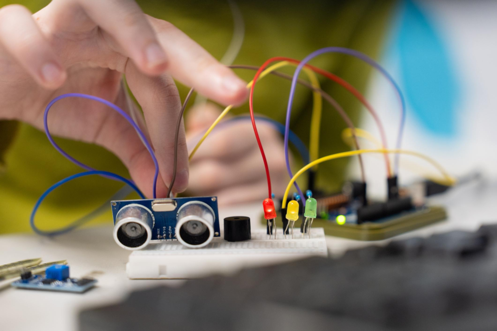
Applications of the Project
The ESP32 Smart Monitoring System can be expanded for many practical applications, including:
- Environmental Monitoring
- Smart Agriculture
- Weather Monitoring Stations
- Industrial Data Collection
- Home Automation Systems
- Laboratory Monitoring
- Educational IoT Projects
- Wireless Sensor Networks
The project provides a foundation for developing advanced IoT solutions.
Advantages of Using ESP32 Smart Monitoring System
The ESP32 offers several benefits for monitoring applications:
- Built-in Wi-Fi connectivity
- High processing capability
- Low power consumption
- Multiple GPIO pins
- Easy integration with sensors
- Cost-effective development platform
- Strong support within Arduino IDE
These features make the ESP32 one of the most popular microcontrollers for IoT projects.
Learning Outcomes
By completing this project, students gain hands-on experience with:
- ESP32 Programming
- Sensor Interfacing
- Arduino IDE Development
- Wireless Communication
- Web Server Creation
- Real-Time Data Monitoring
- IoT System Design
- Embedded Electronics
These skills are valuable for future projects involving automation and smart devices.
YouTube Tutorial
For a complete step-by-step demonstration, watch our detailed video tutorial. The tutorial explains hardware assembly, code configuration, Wi-Fi setup, ESP32 programming, and live data monitoring through a web browser.
In this tutorial, you will learn:
- How to connect the DST module to ESP32
- Configuring Wi-Fi credentials
- Uploading code using Arduino IDE
- Creating a wireless monitoring server
- Accessing live sensor data on mobile devices
- Understanding ESP32-based IoT applications
YouTube Tutorial:
Why Learn with RoboSiddhi?
At RoboSiddhi, we believe in making STEM education practical, engaging, and accessible. Our hands-on projects help students learn electronics, programming, robotics, and IoT through real-world applications.
What RoboSiddhi Offers
- Robotics Projects
- STEM Activities
- Arduino Tutorials
- ESP32 and IoT Projects
- Coding Programs
- Artificial Intelligence Basics
- Electronics Learning Kits
- Project-Based Learning Resources
Benefits of Learning with RoboSiddhi
- Beginner-Friendly Tutorials
- Practical Learning Experience
- Industry-Relevant Skills
- Step-by-Step Guidance
- Innovative Project Ideas
- Continuous Learning Support
Visit www.robosiddhi.com to discover more exciting STEM and IoT projects.
Conclusion
The ESP32 Smart Monitoring System using a DST module is an excellent project for learning IoT fundamentals and wireless data monitoring. By integrating sensor technology, Wi-Fi communication, and a browser-based interface, this project demonstrates how modern monitoring solutions operate in real-world environments.
With its simple setup, low cost, and scalability, the project serves as a strong foundation for advanced smart monitoring applications. Whether used for educational purposes or as a starting point for larger IoT systems, the ESP32 Smart Monitoring System offers valuable hands-on experience in embedded technology and wireless communication.