
This is a complete, website-ready blog for Class 8–12 students and beginners.
After reading this blog, any student can build the project easily without external help.
1. Project Name
LED Blink using Arduino Uno
2. Project Level
Beginner (School Level – Class 8 to 12)
3. Project Objective
The objective of this project is:
- To understand what Arduino Uno is
- To learn how to control an LED using Arduino
- To learn basic Arduino programming
- To understand digital output pins
This is the first and most important Arduino project for beginners.
4. What is LED Blink Project?
In the LED Blink project, an LED turns ON and OFF repeatedly after a fixed time interval.
Example:
- LED ON for 1 second
- LED OFF for 1 second
This project helps students understand:
- How Arduino sends signals
- How timing works in programming
- How hardware and software work together
5. Required Components
| Component | Quantity |
|---|---|
| Arduino Uno Board | 1 |
| LED | 1 |
| 220Ω Resistor | 1 |
| Breadboard | 1 |
| Jumper Wires | 2–3 |
| USB Cable | 1 |
6. Understanding LED (Important)
An LED has two legs:
- Long leg → Positive (Anode)
- Short leg → Negative (Cathode)
If the LED is connected in the wrong direction, it will not glow.
7. Why Do We Use a Resistor?
A resistor is used to:
- Limit current flowing through the LED
- Protect the LED from burning
- Protect the Arduino pin
In this project, a 220Ω resistor is compulsory.
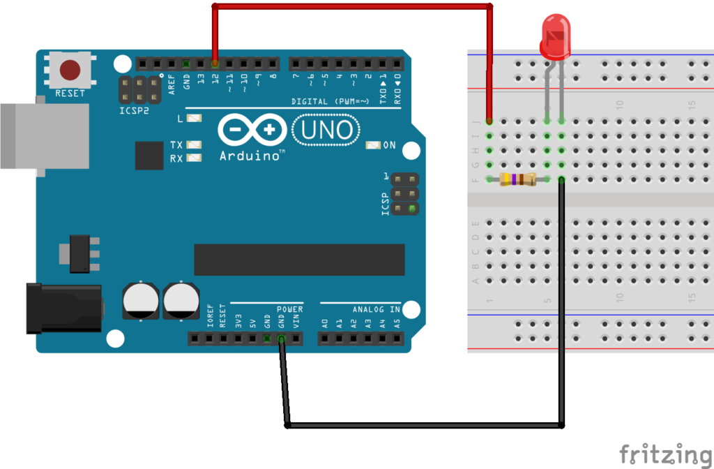
8. Circuit Diagram – LED Blink using Arduino Uno
Below is a clear and student-friendly SVG circuit diagram.
You can zoom it without losing quality and also convert it to PNG for printing.
Circuit Connections
- Arduino D13 → LED Positive (Long leg)
- LED Negative (Short leg) → 220Ω Resistor → GND

9. Circuit Connection – Step by Step
Step 1
Do not connect the USB cable yet.
Step 2
Place the LED on the breadboard.
Step 3
Connect:
- LED long leg → Arduino D13
- LED short leg → 220Ω resistor
Step 4
Connect resistor’s other end → Arduino GND
Your circuit is now complete.
10. Arduino IDE Setup
- Download and install Arduino IDE
- Open Arduino IDE
- Go to Tools → Board → Arduino Uno
- Go to Tools → Port → Select correct COM port
11. Arduino Code
void setup() {
  pinMode(13, OUTPUT);   // Set pin 13 as output
}

void loop() {
  digitalWrite(13, HIGH); // LED ON
  delay(1000);            // 1 second delay

  digitalWrite(13, LOW);  // LED OFF
  delay(1000);            // 1 second delay
}
12. Code Explanation
pinMode(13, OUTPUT);
Tells Arduino that pin 13 will send output.digitalWrite(13, HIGH);
Sends 5V → LED turns ON.digitalWrite(13, LOW);
Stops voltage → LED turns OFF.delay(1000);
Waits for 1 second.
13. Uploading the Code
- Connect Arduino to computer using USB cable
- Click Upload button in Arduino IDE
- Wait for “Done Uploading” message
- LED will start blinking
14. Expected Output
- LED turns ON for 1 second
- LED turns OFF for 1 second
- This repeats continuously
15. Common Mistakes
- LED connected in reverse direction
- Resistor not used
- Wrong pin number in code
- Board or port not selected
16. Real-Life Applications
- Power indicator lights
- Status indicators
- Debugging signals
- Base project for robotics and IoT
17. Viva / Exam Points
- Arduino Uno is a microcontroller board
- LED Blink is the basic Arduino test program
- Delay function controls timing
- Digital pins are used for ON/OFF control
18. Conclusion
LED Blink using Arduino Uno is the best starting project for beginners.
It builds confidence in:
- Arduino hardware
- Programming logic
- Electronics basics
This project is perfect for school practicals, science exhibitions, and STEM labs.